Specifications and Distances of Holes in Bolted Connections
Byمدیر فنی
In bolted connections, it is necessary to drill steel parts correctly and in proportion to the diameter of the bolt. Accuracy in drilling and the integrity of the hole body, as well as observing the distances of the holes from the edge of the part and from each other, play an important role in the strength and load-bearing capacity of bolted connections. Therefore, it is necessary to observe the following requirements in the design and calculation. The tenth topic of the Iranian National Construction Regulations states the allowable shear stresses in friction connections based on the type of hole. According to the definition of the Iranian regulations, a standard hole is a hole whose diameter is 2 mm greater than the diameter of the bolt. While the AISC regulations call a hole standard whose diameter is exactly equal to the diameter of the bolt. From an implementation point of view, the definition of the AISC regulations is not possible, but it can definitely be said that the definition of the Iranian regulations for a standard hole is also very difficult to implement. As a result, in most calculations, the accountants assume that the hole created in the frictional state is non-standard (according to Section B of Section 10.1 and 10.3 and Section 10.3 and 5.3 of the 1387 edition of the tenth topic, connections that do not participate in the seismic system) and consider the controls based on the large hole, and in support connections, they emphasize the standardity of the hole, because in any case, implementing a standard hole is easy in practice.
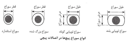
1- Types of holes in bolted connections
- Standard hole
- Enlarged hole
- Long bean hole
- Short bean hole
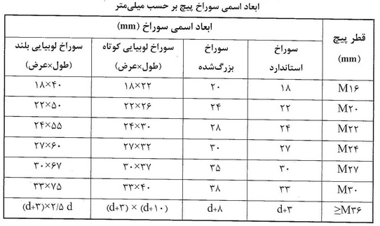
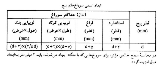
2- Limitation of nominal dimensions of holes and their scope of application
- Maximum dimensions of holes must be according to the table below.
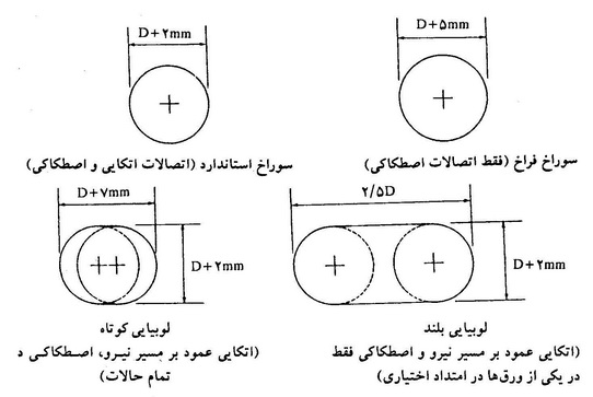
- Enlarged holes are allowed only in friction connections.
- Short bean holes are allowed in all directions in friction connections, but in support connections, the longitudinal direction of the hole must be perpendicular to the direction of force.
- Long bean holes are only allowed in the direction perpendicular to the force path in support connections, but in friction connections they are allowed in all directions, provided that they are only in one of the connection sheets.
Bean and large holes are installed in connections for the following reasons:
a. In support or friction connections in which the prestressing force is reduced or eliminated for some reason. When the connection is subjected to dynamic loads, there is a possibility of the bolt shaft contacting the hole wall repeatedly. Installing large or bean holes will prevent the bolt shaft from contacting the hole wall, especially due to fatigue.
b. Installing large and bean holes provides more suitable conditions for assembly, adjustment and tolerance of the bolts in the connection.
c. Installing large and bean holes prevents the occurrence of temperature-induced stresses as well as second-order stresses.
3- Minimum bolt hole spacing in bolted connections
The center-to-center distance of standard holes, enlarged holes, and bean holes should not be less than 3 times the diameter of the fastener.
The minimum value for the hole spacing is considered for two reasons, one is to prevent the sheet from breaking and tearing, and the other is to ensure the work is feasible and to provide adequate space for fastening the screw. The maximum number of holes is considered for three reasons, firstly, to ensure a more realistic distribution of force in the connection and to create a uniform force in the bolts to ensure that the sheet is rigid, secondly, by reducing the distance, the buckling wavelength resulting from the compressive force is also reduced to the lowest possible value to prevent local buckling, and the last reason is to prevent the joint between the connecting sheets from opening and the risk of sheet rust.
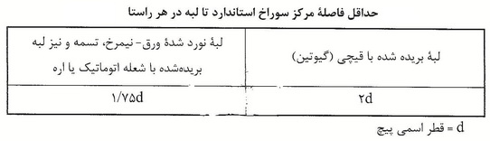
4- Minimum hole-to-edge distance in bolted connections
The distance between the center of the standard holes and the edge of the connected piece should not be less than the values given in the table below.
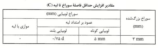
For enlarged holes and bean holes, the distance from the center of the hole to the edge shall not be less than that specified for standard holes plus the corresponding C value from the table below.
5- Maximum distance from the center of the hole to the edge
The maximum distance from the center of each bolt to the nearest edge of the part in each direction is as follows.
- For parts subject to light and moderate corrosion caused by atmospheric factors, the distance from the center of each bolt to the nearest edge of the part in each direction shall not exceed 12 times the thickness of the thinnest part and 150 mm.
- For parts subject to severe corrosion caused by atmospheric factors, the distance from the center of each bolt to the nearest edge of the part in each direction shall not exceed 8 times the thickness of the thinnest part and 125 mm.
6- Maximum distance from the center of holes in bolted connections
The minimum distance from the center of standard, enlarged, short and long bean holes is 3d, where d is the diameter of the bolt. In no case shall the net distance between the two edges of the hole be less than 2d. As a guideline, it is recommended that the center-to-center distance of the holes be no less than 75 mm. The maximum center-to-center distance of the holes is as follows:
- For parts subject to light and moderate corrosion caused by atmospheric agents, the distance between the centers of the holes shall not exceed 24 times the thickness of the thinnest part to be joined and 300 mm.
- For parts subject to severe corrosion caused by atmospheric agents, the distance between the centers of the holes shall not exceed 14 times the thickness of the thinnest part to be joined and 200 mm.
Hole Correction
For the final assembly of the parts, after the marked parts have been arranged on the frame and the connecting plates have been placed over the holes, the parts are fixed in place by means of pins that pass through the connecting holes. In the manufacturing workshop, the alignment of the holes is carefully controlled, but it is still possible that up to 15% of the holes in a location do not perfectly match due to manufacturing inaccuracies. In such a case, these holes must be found by passing a test screw and corrected by reaming. The maximum diameter of the reamer used is 3 mm larger than the diameter of the screw, and reaming should not increase the diameter of the hole by more than 5 mm. The use of flame cutting to enlarge the holes is not permitted.