Introduction to bolt production methods and bolt, nut and washer tests
Byمدیر فنی
Bolts are generally produced by two methods: cold forging and hot forging. The cold forging method has fewer defects and better quality than hot forging. It should also be noted that currently in our country, only up to size M24 is produced by cold forging, which should be considered in design.
Bolt coating methods according to ASTM:
After manufacturing, bolts may be coated to prevent corrosion. Coating methods include:
Cold galvanized or electrolytic coating
Mechanical galvanized coating (which has less technology in Iran).
Hot galvanized or hot-dip galvanized coating
Non-galvanized or colored coating.
ASTM regulations strongly recommend that no metal coating be used for class 10.9 bolts, as hydrogen cracks may occur in the bolt. As a result, it should be noted that non-galvanized coatings are used in corrosive environments. In the galvanizing method, it is during the acid washing stage that hydrogen ions are activated in the bolt steel, while in the non-galvanizing method, shot blasting or steel fine grain spraying is used instead of acid washing.
Bolt, nut and washer tests:
In general, the following tests are performed to test bolts and washers:
Dimensional tests
Metallurgical tests
Mechanical tests
Corrosion resistant coating tests
Dimensional and metallurgical tests are performed at the manufacturer’s factory during the production of bolts and washers. Mechanical tests are performed after the bolts and washers are produced at the manufacturer’s factory or in material strength laboratories. Mechanical tests are important for design engineers and inspectors. In general, mechanical tests include tensile, hardness and impact tests. The tensile test itself includes three types of tests: proof load test, wedge tensile test on a complete sample and tensile test on a machined sample.
Impact test: In the impact test, a sample of the material used is taken, and with the help of a pendulum device and the free fall of the pendulum, the broken piece and the amount of energy absorbed are measured. Impact testing is not mandatory for screws, but it should be done if possible.
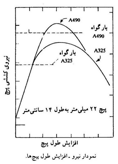
Tensile test: This test is one of the most common screw tests. In the tensile test, after the screw is fully tightened with a nut of a higher strength class on the tensioning device, the screw is stretched at an appropriate speed to the yield stress and then remains in this state for ten seconds. Then the tensile load is removed from the screw. In this test, there should be no breakage or permanent elongation in the screw.
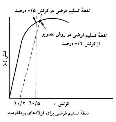
Proof load test: Since high-strength screws are made of high-carbon steels, there is no specific yield point for them. Therefore, in this case, to express the yield strength of the bolt, instead of using the actual yield load, we use the conventional yield load or proof load. The proof load is the load obtained by multiplying the net cross-sectional area of the threads by the stress such as strain 0.2% or the stress such as strain 0.5%. The net cross-sectional area of the threads is obtained from the equation π/4 (d-0.9328p)^2 where d is the nominal diameter of the bolt in millimeters and p is the thread pitch in millimeters.
Wedge tensile test: After the tensile test, this test is performed on the bolt. The regulation requires that the tensile test be performed on a complete and real sample of the bolt and nut used in the project, except in cases where there is a capacity limit on the testing machine or the length of the bolt is very short, in which case a machined sample is used. In this test, at least four complete threads of the bolt must be placed between the jaws of the machine. The maximum speed of the machine must not exceed 25 mm/min. The failure must only occur in the bolt body, and if a failure occurs at the connection point of the bolt head to the body, even if the required strength has been reached, the sample is not accepted. This failure is more commonly observed in bolts made using the hot forging method, and accordingly, bolts made using the cold forging method should be used as much as possible. Since in Iran and currently only up to a diameter of M24 are produced using the cold forging method, efforts should be made in the design not to use higher diameters.
Hardness test: This test is in the category of non-destructive tests of the screw and is performed to determine the hardness of the part and its equality with the standard value. Hardness testing is performed for the end part, the flat surface of the body and the flat surface of the screw head. Generally, three methods are used for hardness testing, which are: Brinell method, Rockwell method and Vickers method.
Hardness testing by Rockwell method
Rockwell is used to measure the hardness of relatively hard metals and is of three types:
Rockwell A, where a force of 60 kg is applied
Rockwell B, where a force of 100 kg is applied.
Rockwell C, which applies a force of 150 kg
Rockwell is available in both ball and needle form. Ball Rockwell transfers the weight applied to the metal by a metal ball, but needle Rockwell applies this force to the metal with the help of a needle, whose point of effect will be a 120-degree cone. The point of effect of Rockwell types A and C is a 120-degree cone, but Rockwell B does not have a ball and has a pyramid-shaped needle with an angle of 120 degrees, whose point of effect is a square. The Rockwell testing machine is a rapid testing machine with direct reading. This method is very suitable for performing rapid comparative tests. In these tests, the depth of the indentation is measured and read directly by a pointer on a circular graduated dial that is indirectly divided into 100 divisions (each division represents 0.01 mm of the depth of the hole). In this method, a small number on the dial means a large depth of indentation and, consequently, a low hardness (soft material) and vice versa. There are several sets of Rockwell hardness scales because several standard indenter and indenter are used for the test. The indenter are hardened steel balls of various diameters or a diamond with a 120 degree apex angle. Standard spherical indenter have diameters of 1/16 inch, 1/8 inch and 1/2 inch. Standard loads are 100, 60 and 150 kg. Each Rockwell hardness scale is designated by one of the letters A, B, etc. When an indenter is compressed by a force within a material, both elastic and elastic strains are observed. However, since indentation hardness is the resistance to elastic deformation, the elastic force must be removed before reading the hardness. Of course, to ensure that the reading is correct, a small indentation force is applied to the indenter when reading to ensure complete contact of the indenter with the bottom of the indenter. This is achieved by applying a partial (low) force and a total (high) force. The method of using these two forces in the hardness testing procedure is as follows:
The sample is placed in contact with the indenter. The sample is brought close enough to the indenter to move the small pointer of the display to a predetermined position on the screen. By doing this, the indenter compresses a spring until the force exerted by the spring on the material through the indenter reaches 10 kg.
The display is set to the correct reference (zero for diamond indenter and 30 for spherical indenter) and the desired primary force of 100, 60, and 150 kg is entered.
The total force is maintained for 4 to 7 seconds.
While maintaining a partial force on the sample, the total force is removed until an elastic texture is obtained.
The hardness number is read from the display.
The highest degree of confidence in the test results is when the hardness number is between 20 and 70. If the sample is too thin, the result will not indicate the true property of the material. The different Rockwell scales overlap with each other. It is important to choose the right combination of indenter and pressure force for the material in question. The depth of the hole should not exceed 100 degrees of the display. When reporting the Rockwell hardness number, the relevant scale must be mentioned with the number. Otherwise, the hardness number will be meaningless. There are other Rockwell hardness scales, which are the T and N scales. And other types of scales are A and B. But with a lower indentation force which is applied to test thin specimens. The scales used with conical indenters are N30, N45 and N15. The scales used with 1/16 inch steel ball indenters are called T45, T30, T15. In each case the first number represents the main force applied to the indenter in kilograms. The method of performing the T and N tests is exactly the same as the methods described with the same partial force of 10 kilograms before the main load is applied.
Brinell Hardness
Brinell is a hardness testing method with a ball mechanism. The European standard for this test is DIN50351. The balls used in Brinell are usually 5 and 10 mm. In Iran, Brinell is most commonly used for forces of 187 and 250 kg. In the steel and steelmaking industry, the Brinell method is used with a force of 3000 kg and a 10 mm ball. Other areas of application of Brinell include casting. To measure the hardness of metallic materials, this method uses a static force of 500 to 3000 kg and a hardened steel ball or ball with a diameter of 10 mm. For very hard metals (usually 400 to 600 Brinell), tungsten carbide balls are used. Usually, for non-ferrous and softer metals such as copper and aluminum alloys, a force of 500 kg is used, and for hard metals such as steel and cast iron, a force of 3000 kg is used. After the ball penetrates, the force is continued to be applied for a certain period of time (10 to 15 seconds for cast iron and steel, about 30 seconds for soft metals) until complete deformation of the indentation occurs. The indentation is then measured with a graduated microscope. Usually, two orthogonal diameters of the indentation are measured and their average is used to calculate the hardness number.
The indentations created by a spherical indenter are not similar in terms of geometric shape, and each indenter creates two types of indentations.
Deep
Shallow
Since these two types of indentations are not similar in terms of geometric shape, the indentation flow pattern in a deep indentation is different from the indentation flow pattern in a shallow indentation. That is, the resistance to deformation of the two indentations is not the same. Therefore, this hardness number obtained from the Brinell test is not independent of the applied force. In other words, if two Brinell hardness tests are performed on the same material with two different forces, the hardness number obtained from a higher static load and the hardness number obtained from a lower static load will be different. In a shallow indentation, the diameter of the hole (d) is small compared to the diameter of the ball D. The angle between the sample surface and the tangent to the tube sheet is very small and the boundary of the indentation is not well recognized under a microscope. As a result, the diameter of the indentation cannot be measured accurately. In a deep indentation, the boundaries of the hole are well defined. However, although the diameter can be measured accurately, a significant increase in the depth of the hole and, consequently, the contact surface, does not cause a large increase in the diameter d. This, in turn, reduces the accuracy of the hardness measurement. As a result, the Brinell method is not suitable for very hard materials. As the hardness of the material being tested approaches the hardness of the spherical indentor, the possibility of deformation of the indentation arises. The Brinell test is suitable for testing materials up to a hardness of 400 and is not recommended for metals with a hardness higher than 500.
Vickers Hardness
This test was introduced and used in 1924. In this test, the penetration of a square pyramid with an angle of 136 made of synthetic diamond is used. The reason for choosing an angle of 136 in this test is that it is close to the most desirable ratio of the indentation diameter to the diameter of the bullet in the Brinell hardness test. This test leaves a smaller mark on metals and is more suitable for soft metals. The Vickers hardness test is used for research work due to its high accuracy. Vickers is mostly used in the automotive industry and the range of weights that are most commonly used is 5, 10 and 30 kilograms.
Vickers is of two types:
Micro Vickers, which is used in gram weights up to 1 kg
Macro Vickers, which is used in weights from 2 to 120 kg
Vickers, like a micrometer, measures the depth of the indentation. Since the range of use of micro Vickers in weights is very small, devices that perform measurements using the micro Vickers method must be placed in an isolated environment. In the Brinell test, since the shape of the bullet also changed elastically due to the applied force, the hardness depended on the applied force, and hence the P/D2 ratio was important. However, in this test, since the small diamond pyramid does not deform and the shape created in the test sample does not depend on the applied force, the answers obtained are more accurate and more recognizable. For example, Vickers hardness 600 is twice the Vickers hardness 300. However, this scale and proportion are not established in the Brinell test. The international standards for this test are ASTME92, DIN50133. The Vickers hardness number (HV) is determined by the area of the indentation. In practice, this area is calculated from the microscopic values and the diameters of the impact. In this test, by obtaining two diameters, the average of them can be calculated and the hardness of the part can be extracted using the available table. The amount of force in the Vickers test is less than the force used in the Brinell test and increases as the sample becomes harder. This force is usually between 5 and 30 kilograms, and for high forces, for example above 125 kilograms, care must be taken so that the diamond of the device is not damaged.
For the nut, a tensile test is not used and only proof load and hardness tests are performed on the nuts. For the washer, only a hardness test is performed.
Sources and references:
Design guidelines for steel bridges – Publication No. 395-(2007)
Regulations for connections in steel structures – Publication No. 264-National Planning and Management Organization-2006
National Building Regulations – Topic Ten – Design and Construction of Steel Buildings – Fourth Edition 2013
Pishgaman Pich Pars website – Author Mohammad Reza Karimi
Kar o Andisheh Shop website – Author Engineer Khodayari