Welding Defects
Byمدیر فنی
Achieving a satisfactory welded joint requires an organized process that begins with the design of the joint and the selection of the welding method and ends with the welding operation and its inspection. The structural designer must be aware of the factors affecting the quality of welding and use them in his joint design.
To achieve a good weld, the following five factors must be met:
1) Welding method (Process selection)
2) Seam preparation (Preparation)
3) Welding instructions (Procedure)
4) Personnel (Personnel)
5) Inspection and verification of the weld (Prove)
The above set of instructions is called the Five P’s rule. If the correct welding methods and techniques are not followed, defects may occur on the surface or inside the weld metal. Here we will examine the main welding defects, their causes and ways to prevent their occurrence.
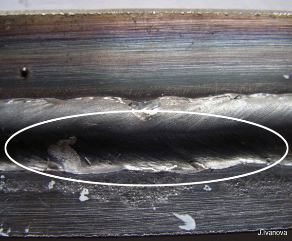
Lack of fusion (L.O.F)
Lack of fusion)
Lack of connection between the weld metal and the base metal or between the weld passes.
Factors causing defects:
1) Failure to select the correct size and type of electrode, for example, using small electrodes for thick and cold steel
2) Insufficient amperage and insufficient input energy: When the welding amperage is low, the heat in the piece is less and as a result, the melting process is not completely performed. On the other hand, when the amperage in welding is low, the electrons that enter the piece from the electrode are less and the action of the electrons is not completely performed in the base piece and therefore causes the defect (insufficient melting).
3) Improper electrode angle: Whenever the angle of our electrode is more inclined towards a piece, the melting process is more performed in that piece and vice versa in our other piece. For this reason, full attention should be paid to the angle of the electrode during welding so that the melting process is performed evenly between the two pieces to be joined.
4) Very high speed of movement: When the welding speed is high, the electrodes that hit the metal from the electrode and cause the metal to be pierced do their job faster, but on the other hand, the molten droplets that want to fill this drilled channel cannot do their job completely and are not covered by molten droplets in some parts of the weld pool, and as a result, those parts remain empty and cause the defect of insufficient melting.
5) Lack of cleaning between passes and dirty surface (rolling scale, stains, oil, etc.)
6) Inappropriate connection design
7) Insufficient shielding gas in gas-shielded processes
8) Arc deviation: When our arc deviates, the arc balance is disturbed and when the arc deviates to any side, the other side is not bombarded by electrons and as a result, it does not melt. Similarly, melting in welding is not done completely.
9) Electrode polarity: When we only have access to one side of the workpiece, we must choose a polarity in welding so that our melting process is complete. The most penetration in DC welding is with a direct polarity (negative electrode, two positive workpieces).
Result: The weld joint remains weak and becomes a fatigue-prone area.
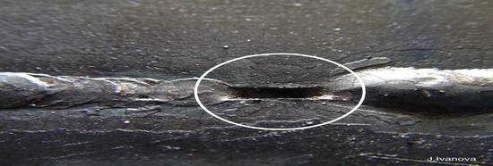
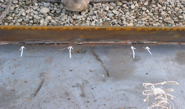
Lack of Penetration (L.O.P)
Incomplete penetration of the weld metal into the root of the joint
Factors causing the defect:
1) Very low amperage
2) Insufficient root distance
3) Use of a large diameter electrode
4) High speed
5) Improper hand angle
6) Dirty seam
7) Low bevel angle
Result: Weakening of the joint and consequently creating a zone prone to fatigue and ultimately causing the part to break.
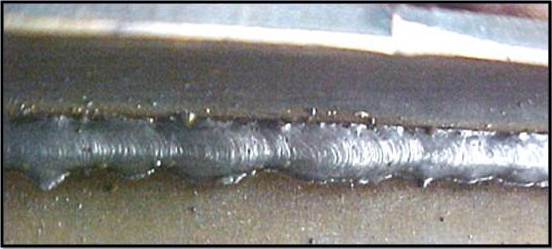
Undercut
A groove on the side or edge of a weld that is located on the surface of a weld or previously deposited weld metal. Which is seen intermittently or continuously with great depth throughout the weld path.
Factors causing the defect:
1) High amperage
2) High arc length
3) High wave motion of the electrode
4) Very high welding speed
5) The angle of the electrode was too inclined to the joint surface.
6) High viscosity slag
Result: The above factors cause a stress concentration zone and a zone prone to fatigue cracking. Which eventually leads to the onset of failure or fatigue or cyclic stresses.
To prevent this defect, we must make a suitable zigzag motion with short pauses at the edges of the joint edge and slightly reduce the speed of welding progress.
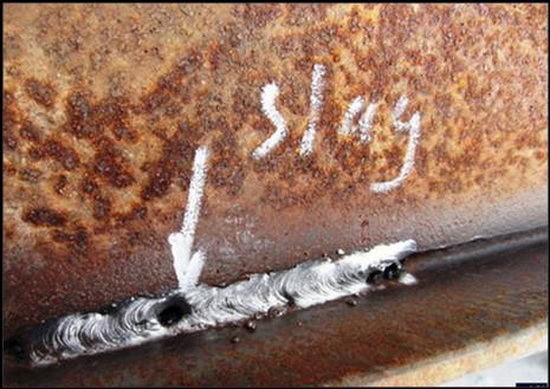
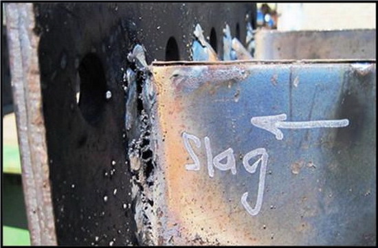
Slag inclusions
Any non-metallic material that forms in a welded joint is called slag inclusions; these inclusions can create weak spots in the weld deposit. The source of these particles is not necessarily the electrode or slag coating, but can also be the product of various slag, gas, and metal reactions.
Factors causing defects:
1) Inadequate cleaning of slag from previous passes
2) Insufficient amperage
3) Incorrect electrode angle or size
4) Improper preparation
5) Dropping of broken electrode shell into the melt
6) Air entering due to the welder’s negligence in improper electrode or torch movements
Result: Slag inclusions reduce the strength of the weld cross-section and create a crack-prone area. A small amount of these particles does not have much effect on the mechanical properties, but a large amount, especially large and long dimensions, have a negative effect on the mechanical properties, especially the impact strength of the weld metal.
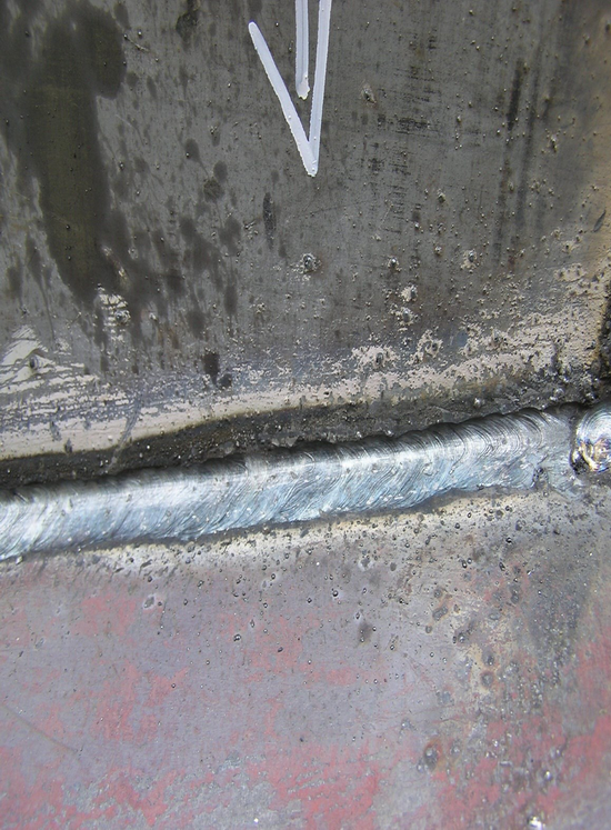
Overlap or over roll:
A defect in the side or root of a weld that occurs due to the metal flowing over the surface of the base metal without melting and fusing with it. This defect occurs more often in manual electrode welding and in a vertical position, usually due to the incorrect angle of the electrode or workpiece.
Factors causing the defect:
1) Slower than normal travel speed
2) Incorrect electrode angle
3) Using a large diameter electrode
4) Too little amperage
Result: Overlap causes the weld to be cut off and creates a stress concentration zone of unfused weld metal.
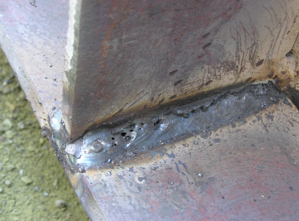
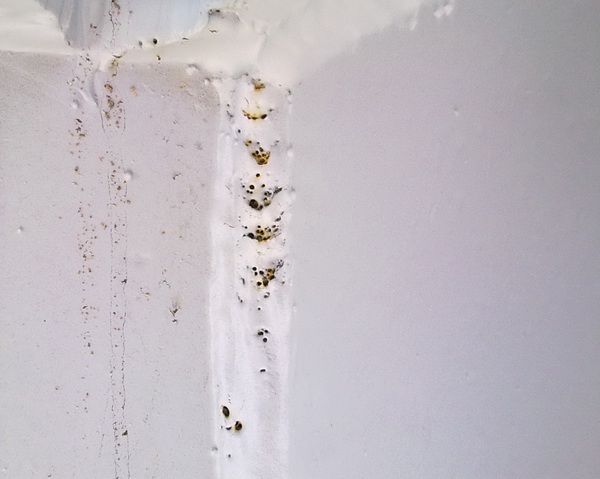
Porosity
Porosity is a cavity or hole that appears internally or externally in the weld. Porosity can be caused by a wet electrode, a broken electrode coating, or by impurities on the base metal. Porosity can also be seen as tubular pores, surface pores, and wormholes.
Defect Causes:
1) Contaminated base metal surface such as oil, dust, dirt, or rust
2) Wet electrode coating
3) Insufficient arc shielding gas
4) Base metals with high sulfur and phosphorus levels
5) Insufficient time for metallurgical reactions in the weld pool
Result: Severely reduces the strength of the welded joint. Surface porosity allows the corrosive atmosphere to attack the weld metal and cause defects.
- Defects and voids that are observed in the first few centimeters of welding with some electrodes: This defect is due to the lack of sufficient deoxygenation at the beginning of welding. The electrode coating usually contains some deoxygenating materials such as ferrosilicon. In high-strength alloy steels, the percentage of silicon in the weld should usually not exceed a certain amount (about 0.35%) because it has an adverse effect on the transition temperature from softness to brittleness in impact strength. Therefore, there is a limitation in the electrodes used in such steels such as the E100, E110 and E120 series in terms of the presence of ferrosilicon and sometimes some other deoxygenating elements. However, with the progress of welding operations and the greater and more active presence of slag from the electrode coating, the presence of the air atmosphere in the weld pool area naturally decreases and this defect does not occur. In this case, various measures have been foreseen to avoid the occurrence of this type of defect, which are briefly explained below.
A: Start the welding operation on the steel scrap that has already been attached at the beginning of the welding path and is separated from the workpiece after the welding is completed. It is clear that this measure may not be economical in some cases.
B: Back-step technique: The starting point is slightly behind the actual starting point. After the start of welding, the electrode is guided to the beginning of the connection path and the welding operation continues. In this way, if there is a void, it is most likely to be eliminated by returning the arc and remelting it.
- Imperfections in the freezing range: This type of voids may be observed throughout the weld and has two types of shapes: spherical voids that are concentrated or scattered under the weld or even on the weld. The other type is called “worm”-shaped holes or blow holes.
Some gases have solubility in the melt, and at high temperatures this solubility increases. An example of such gases is hydrogen, which is the result of the decomposition of moisture introduced into the molten weld metal. In the meantime, as the melt cools, after the hydrogen volume in the melt has exceeded the saturation limit, the excess amount begins to germinate, grow, float and, if possible, exit the melt in the form of bubbles. There is also the possibility of hydrogen reacting in excess of the saturation limit with C, O and S and producing other molecular gases such as H2O, SO2 and CH4, etc., in which case the reaction product is released from the melt in the form of bubbles or is trapped.
Nitrogen absorbed from the air also behaves somewhat similarly and can be a cause of porosity. In addition, nitrogen can produce tritide compounds that often have a negative effect on the mechanical properties of the weld.
Another cause of gas bubbles is CO. In the weld metal of carbon steels (especially high carbon), dissolved oxygen may usually be present. In the solidification range, the melt, enclosed in the solid, is enriched due to the separation of carbon and the possibility of the following reaction increases.
C+O= CO
In cases where there is not enough oxygen scavenging materials such as Si Mn etc. The above reaction is accelerated. A similar reaction can also occur in the case of sulfur, which results in SO2 or SH2 gas bubbles. Some volatile organic or inorganic compounds present in the mineral materials of the electrode coating and welding powder or contaminants (such as grease, paint, etc.) on the surface of the connection path, as well as the decomposition of compounds such as carbonates in the material composition at high temperatures, are other factors in the formation of gas in the weld pool and finally pores.
Considering the above points and the way the heat is distributed in the weld pool (high temperature under the arc or flame and low temperature with a high slope at the end and the wall of the weld pool) and the growth of solid columnar crystals from the walls towards the middle and the surface of the weld pool, it can be predicted that at the freezing level the gases become saturated and the excess of this amount germinates and grows in the form of bubbles on the solid grains. Under suitable conditions, with a long freezing distance, low viscosity of the melt, and sufficient time, bubbles can come to the surface of the melt and come out. In cases where conditions are not suitable, the bubbles float or are trapped in the growing solid grains during their development and remain as pores or worm-shaped holes in the weld metal. As can be seen, the gas bubble tries several times between the columns of solid crystals to separate into a sphere and float to the surface of the melt, where the continued growth of other solid crystals traps it and finally takes on a worm-like shape. These holes may continue for several millimeters and even to the weld surface.
Another type of pores and holes during melting and freezing is caused by the welder’s negligence in using electrodes whose coating has been broken and separated, or in order to save money, he has also used the end part of the electrode that is not coated.
To reduce voids during solidification, one should not assume that if the temperature of the melt is increased with the help of welding parameters, the viscosity will be reduced and the bubbles will be released better because increasing the temperature also increases the solubility of gases in the melt. Therefore, the only way to prevent the entry of gases or eliminate gas-generating factors such as moisture, grease, etc. is to.
For example, by preheating the electrode or choosing the appropriate type, the amount of hydrogen entering can be reduced by reducing the arc length, the possibility of oxygen and nitrogen entering, by choosing a better type of steel (with less sulfur), the chance of SO2 and SH2 formation can be reduced, and by choosing an electrode with more oxygen-removing materials (in the coating), the possibility of CO2 formation can be reduced.
In processes where shielding gas is used, the measures are slightly different. The combination of shielding gas pressure and flow rate, nozzle diameter, nozzle distance to the work surface, and other parameters must also be carefully considered.
Join Misalignment
This problem is commonly referred to as misalignment or misalignment of the parts being welded. Misalignment is a common problem in butt weld preparation and occurs when the root and base metal joining plates are not in the correct positions for welding.
Causes:
1) Improper assembly of the parts to be welded.
2) Insufficient weld bead that breaks or insufficient clamping that causes movement.
Result: Misalignment is serious because defects in root edge fusion create stress concentration zones that can lead to premature fatigue failure of the joint in service.
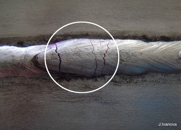
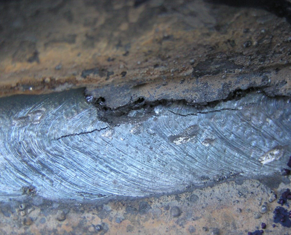
Weld cracking
Cracking is one of the most important and harmful defects in welding. On the one hand, it is likely to occur in a wide range of steels, metals and non-ferrous alloys. On the other hand, the issue is complex because, firstly, it has different shapes, dimensions, directions and sizes. Secondly, it is created in different places of the weld metal, the fusion line and the area adjacent to the weld Heat affected zone (HAZ). More importantly, various reasons such as the chemical composition of the consumables (workpiece metal, wire or electrode powder or flux and shielding gas), welding parameters (amperage, voltage, speed, polarity), the design of the part and the joint, and the practical and technical conditions in welding can cause aggravation or reduction of a particular type of cracking. Schematically shows different types of cracking in different areas, which are known by specific names according to their location and extension, and include:
1) Cracking in the weld pool or end opening (Weld metal crater cracking)
2) Transverse crack in the weld (Weld metal Transwerse cracking)
3) Transverse crack in the area adjacent to the weld (H.A.Z Transwerse cracking)
4) Longitudinal crack in the weld metal (Weld metal longitudinal cracking)
5) Toe cracking (Toe or corner cracking)
6) Cracking under the weld metal (under bead cracking)
7) Cracking in the fusion line (Fusion line cracking)
8) Weld metal root cracking (Weld metal root cracking)
One of the important consequences of cracking is often the breakage of the piece without changing the plastic shape, which is called brittle fracture. This type of fracture is due to the slow initial progress of the crack and after it continues to a certain extent (critical crack length limit), it progresses very quickly and the crack continues in a short time without the need for stress and the fracture occurs. As a result, at this stage, the opportunity to prevent the fracture and complete rupture of the connection is small, and sometimes the speed of crack progression reaches several meters per second, leading to tragic accidents with great financial and human losses, such as a ship breaking in half at sea.
- Hot cracking or super-solidification: Two conditions or states are necessary for a crack to occur in the freezing range in the weld. First, the ductility of the metal must not be sufficient, and second, the tensile stress created between the solid crystals due to contraction must exceed the fracture stress of the metal at that temperature. During cooling, the solid crystals germinate and grow, and the concentration of some elements and impurities in the remaining liquid phase increases. From a certain temperature onwards, the connection of the solid crystals is a kind of adhesion, which shows strength between the crystals, but softness and flexibility are zero. Further, cooling from another certain temperature, the nil-ductility temperature, the flexibility property is also evident, which increases with a large slope with the cooling of the solid. This increase decreases again after a maximum. The temperature gap is called the brittleness, which is an important factor that determines the sensitivity of the metal to cracking.
Brittleness in the freezing zone is due to the presence of liquid layers between the discontinuous grains of the solid. This phase can be a eutectic phase or the result of the accumulation of impurities. When this layer is formed, the liquid has the property of wetting the grains or, in other words, the surface energy is low compared to the grain boundaries. Therefore, manganese sulfide, which tends to become spherical, helps to reduce the sensitivity of the metal to this type of cracking. The stress resulting from contraction during cooling is equal to E, Young’s modulus, the coefficient of thermal expansion, x, the restraint factor, and the temperature change. The probability that this stress exceeds the tensile strength at a relatively large distance is high, and since there is no softness, cracking or failure occurs.
The factor x should also be considered, which depends to a large extent on the non-uniform connection design of the welded skeleton, the distance between the edges of the welded sheet, the thickness of the sheet, and the ratio of the thickness of the sheet to the weld cross-section.
Cracking in the end opening of the weld metal is one of the types of hot cracking. The end opening cools faster than other parts of the weld metal. Also, solidification starts and continues from all sides. The possibility of shrinkage cracks and the resulting shrinkage cracks increases. To reduce or prevent this defect, it is better to prevent the formation of a pool or end opening at the end of the weld path. By taking a step and increasing the distance of the electrode from the work surface, increasing the speed or gradually reducing the current intensity or increasing the wire feed (TIG or oxyacetylene welding process), this opening can be made as flat or shallow as possible.
Cracking of the melting line or penetration and even bursting in the area adjacent to the weld may also be of the hot cracking type. Some alloys contain elements or impurities that produce a phase at the grain boundary that either has a low melting point or causes the strength between the grains to decrease at relatively high temperatures. Sulfides, carbides with complex composition or intermetallic compounds are considered to be these materials. Now, if these alloys are subjected to a welding thermal cycle, the temperature is very close to the melting zone of about 1150-1300 degrees Celsius, the layer between the grains melts and, with low strength and formability at this temperature, is subjected to stresses caused by the contraction of the weld metal, resulting in hot cracking.
Due to air penetration and oxidation of the crack surface at relatively high temperatures, the apparent section of the fracture in hot cracks is often brown (in the case of steels). Sometimes by observing this color, the fracture temperature can be estimated.
Hot cracks can also be caused by trapped slag particles (slag). Most electrodes or fluxes contain substances in their composition to create a slag with a specific gravity and low melting point. In this way, the possibility of slag particles being trapped in the weld metal is reduced.
Cracking along the length of the workpiece near the joint position has also been observed. This is due to the presence of elongated slag particles in the workpiece metal, which were formed during the preparation and rolling of the steel. This type of crack is common to Lamellar tearing.
- Cold cracking or below the freezing line: When the crack continues across the grains and there are no signs of a tendency for the crack to progress at the grain boundary. The crack is most likely a cold or subfreezing type. As mentioned, hot cracking usually occurs above 1200°F (650°C) during welding or cooling. Further cooling to 600°F (316°C) often produces cracks. However, below this temperature, cracks may develop and grow within an hour, days, or weeks after welding, and are called cold cracks.
The conditions required for cold cracking are similar to those for hot cracking: the combination of brittleness in the weld metal or its adjacent area and the tensile stress due to separation (or other factors) exceeding the brittle failure stress limit. This may occur for a number of reasons, including the presence of phases in some alloys that melt during heating (due to welding) and produce localized, brittle areas after solidification and cooling. In some other cases, the phase change due to the thermal cycle caused by the welding operation causes brittle and fragile areas, which is the creation of martensite in some steels or filling of this sample.
Due to the interaction of several factors such as the type of consumables, the welding process, the thermal gradient, the stress distribution, the loading rate, the corrosive environment, etc., it is very difficult to accurately diagnose or the real causes of cracking. Often, cold cracking due to a factor resulting from freezing can also later result in cold cracking due to aggravating factors at low degrees. In general, the conditions that increase the likelihood of cold cracking are:
1) Embrittlement and hardening of the area adjacent to the weld
2) Creation and progression of reactive and residual stresses
3) Hydrogen embrittlement
The microscopic structure of the workpiece steel is one of the important factors in cold cracking.
Sometimes the stress created is not so great as to cause cracking, but remains in the part as residual stress, and during the use of the part under certain conditions of applied force and stress, the sum of them exceeds the rupture stress limit and cold cracking and premature rupture begin. Therefore, heat treatment with post-heating may in some cases prevent the formation of cold cracking. Preheating is another useful measure to reduce the cooling rate and prevent the formation of a brittle phase.
As previously mentioned, in addition to the improper microscopic structure, the effect of reaction and residual stresses is also important. Cracking may be caused by reaction stresses that do not have the ability to change formability. Often in thin sheets, the stresses are biaxial and in thick sheets, they are triaxial. One of the factors that intensifies the stresses at the joints is a crack or seam. The stress created at the root of the crack increases with increasing crack depth.
Incomplete penetration of the weld root in a one-sided butt-to-butt connection is also a factor that intensifies root cracking.
High weld pool height as a result of a small weld corner angle Reentrant angle and under-cut or burn of the weld edge Under cut can intensify and concentrate stress in a specific and small location, which will probably result in a corner crack.
The third factor that affects cold cracking is the amount of hydrogen in the weld (often enters the melt through moisture and fats). The theory and mechanism of hydrogen embrittlement are very detailed and complex, which is reviewed briefly.
Due to the small size of hydrogen atoms, this element can be easily dissolved in steel and penetrate into the atomic lattice of iron in the solid state and move from one place to another. The strong effect of hydrogen embrittlement on the formation of cold cracks is not a new topic, as the effect of hydrogen on embrittlement has been studied in wire and spring manufacturing.
Now, if the weld metal deposited on steel with a hand electrode is considered, about 100 gr/ml30 (percentage of grams of weld metal) of hydrogen may be dissolved in the molten weld metal, which at the same time as the melt cools, the solubility of the gas decreases and some of the hydrogen is released as molecules of other gases. However, due to the cooling of the molten weld metal, some of the hydrogen gas is trapped in the weld, which reaches saturation during further cooling. Some of the hydrogen atoms penetrate to the surroundings and even reach the surface of the metal and are released. The rest of it is transferred to the crystal structure or the steel bonding network where there is less dissolved hydrogen or to any other free space including discontinuous drilling of the crystal structure discontinuities within the metal. It is clear that this rate of penetration also decreases with decreasing temperature.
Considering the above points, it can be said that the amount of residual hydrogen in the weld metal depends on the degree of hydrogen influence on the following characteristics:
1) Reaction with oxygen, carbon, sulfur and possibly other elements and the formation of a gaseous compound
2) Penetration into the pores and their molecular or bubble formation
3) Entry into the empty space around the impurity particles and possibly in the form of water (oxide)
4) Adsorption to the area adjacent to the weld
5) Penetration to the surface and release into the air
It is clear that the interpass temperature and the time the weld is held at ambient temperature or possibly at elevated temperature can affect the residual hydrogen and the above.
There are various theories about the mechanism of hydrogen embrittlement. The first theory states that supersaturated atomic hydrogen dissolved in the crystal lattice can precipitate on the surface of small holes or tiny joints between impurities at grain boundaries (Perfection) or tiny joints around impurity particles (rifts and voids). In these very small positions, hydrogen changes from atomic to molecular and, due to the square relationship between molecular pressure and atomic pressure of the absorbed hydrogen, a lot of pressure is created in these small holes and joints. For example, 1ml/100gr of absorbed hydrogen can produce a pressure of about 200,000 psi. It is believed that this pressure can create the three-dimensional stresses necessary to create a source sensitive to failure.
Another theory holds that the deposition and separation of hydrogen on the surfaces of internal lattice imperfection rifts reduces the surface energy and lowers the stress, which can cause submicroscopic rifts to expand and rupture. Both theories are based on the stresses resulting from hydrogen diffusion and deposition.
The general belief is that hydrogen embrittlement and the resulting cracks occur in three stages:
1) Incubation
2) Slow crack growth
3) High-speed crack growth even into areas with little hydrogen.
Hydrogen tends to concentrate in areas of triaxial stress where the cohesive strength is low. For example, in areas around defects such as hairline cracks or surface cracks, when the concentration and accumulation of hydrogen in these stressed areas reaches a certain level, a crack point is created and its growth may stop in places with higher fracture strength, but as soon as the three-dimensional stress zone stops, re-cracking and hydrogen concentration begins, and this cycle is likely to repeat until the critical crack length is reached.
The degree of embrittlement produced by hydrogen depends to some extent on the strength of the steel. In general, embrittlement for a given amount of hydrogen increases with increasing steel strength. For example, very strong steels (strength of about 300 Ksi) can become brittle and brittle even with 1 ml/100gr of hydrogen, and this effect is evident.
As mentioned, one of the factors is the penetration and mobility of hydrogen from one area to another, and this factor is itself affected by temperature. In practice, the maximum effect of hydrogen embrittlement has been observed between 150 and 200 degrees F. At high temperatures, the amount of diffusion is such that hydrogen can escape from the metal surface.
The rate of stress application and the thickness of the part are other factors that are not without importance. In considering the formation of cold cracks in welding, it should not be forgotten that at a maximum stress level, hydrogen embrittlement occurs without interruption after the weld cools from about 200 degrees F, and at a minimum stress level, this type of cracking does not occur in a static state. Between these two stress levels, this phenomenon is likely to occur with a delay.
An example of cold cracking caused by hydrogen is often seen under the weld metal in a very close area called underbead creaking in alloy steels, which, depending on the distribution of residual stresses, the location of the stress raiser, or the forces applied in different directions, can even progress and be observed from the area adjacent to the weld to the workpiece metal at a distance.
However, hydrogen can also embrittle the weld metal and cause a type of cold crack. This defect, called fisheyes, has been known for a relatively long time. Fisheyes are usually surrounded by a type of discontinuity resembling gas pockets with trapped non-metallic particles.
Apparently, when hydrogen atoms precipitate on the surface of the pores or microcracks and become molecular, the resulting pressure can be large enough to cause a longitudinal change or stretching in the crystal lattice around the hole. This stress zone may not be as severe as that caused by a sharp crack or crack that continues to crack, but this localized stress zone can cause more hydrogen to penetrate into this area. When the weld metal is subjected to force or strain at a relatively slow rate (under tension or bending), more hydrogen will penetrate into the surrounding area of the hole and these localized areas and surfaces will break flat with brittle failure. Due to the short time, the hydrogen embrittlement mechanism will not be possible in all areas and the remaining areas will rupture with some deformation and the appearance of the fracture surface will be seen in a different way.
To reduce the formation of fish eyes, it is sufficient to heat the part before testing at a temperature between 1300-200 degrees Fahrenheit (700-900 degrees Celsius) for a certain period of time. Naturally, lower temperatures and greater thickness require more time. In this way, some of the hydrogen will escape under the laws of diffusion. The fractured section of the impact test specimen shows a smaller number of fish eyes, confirming the mechanism mentioned above.
In general, three basic measures are considered to prevent or reduce the possibility of hydrogen-induced cold cracking.
A- Using consumables and welding processes with low hydrogen, in manual electrode welding, the use of alkaline electrodes and preheating the electrode can lead to a reduction in hydrogen in the weld metal to some extent. But other welding processes may reduce the amount of hydrogen to a minimum depending on the conditions and facilities. For example, the electron beam welding process
B- Allowing the release of gas from the metal. Sometimes, with post-heating operations, controlling the temperature between passes, hydrogen can be given a chance to penetrate to the outside in large quantities. In some processes, creating a vacuum during welding is necessary. Reducing the external pressure facilitates the release of gases, including hydrogen, and reduces its amount.
C- Controlling the microscopic structure, the amount of carbon and internal or applied stresses.
So in general, it can be said that hot cracks are cracks that occur at high temperatures and are usually related to solidification. Cold cracks are cracks that occur after the weld has reached room temperature and may even be related to the HAZ. Most cracks are caused by the physical stresses of shrinkage, which are usually associated with stretching or deformation of the body during cooling of the weld. If the shrinkage is limited, these physical stresses of strain create residual internal stresses, which lead to the formation of cracks. There are actually two opposing forces:
1) The stress created by shrinkage.
2) The strength and hardness of the base metal
The stresses caused by shrinkage increase with the increase in the volume of metal that has undergone shrinkage. Large welds and processes with high penetration increase shrinkage strains. The stresses caused by shrinkage strains increase with the increase in the strength of the filler metal and the base metal. Also, when the yield strength increases, the residual stress must also increase.
1) Welding Necessity
2) Preheat
3) Inter-pulse Temperature
4) Post-weld Heat Treatment
5) Joint Design
6) Welding Methods
7) Filler Materials
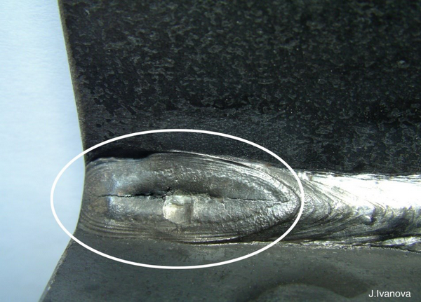
Centerline Crack
A centerline crack is located in the center of a given weld pass. In the case of multiple passes where there are several passes per layer, the center crack may not be geometrically located in the center of the joint. Although it is often seen to be located in the center of the joint. The cause of a center crack is one of the following three phenomena:
1) A crack that is caused by separation and segregation.
2) A crack that is related to the shape of the weld bead.
3) A crack that is related to surface changes.
Unfortunately, all three of the above phenomena manifest themselves in the same way and it is difficult to identify the crack. Furthermore, experience has shown that often 2 or even 3 of the above phenomena interact and contribute to the formation of cracks. In fact, understanding the main mechanism of each type of central crack helps us to find a solution to eliminate the crack.
Central Crack Due to Segregation
These cracks occur when low-melting compounds such as phosphorus, zinc, copper and sulfur segregate at certain points during the cooling process. During the solidification process, low-melting compounds in the molten metal are pushed to the central areas of the joint because they are the last compounds to start solidifying and the weld in these areas tends to segregate and separate. In welding, electrodes with high manganese content can be used to overcome the formation of low-melting iron sulfide. Unfortunately, this concept cannot be applied to other non-volatile materials except sulfur.
Central Crack Due to Weld Slag Shape
The second type of central crack is a crack caused by the shape of the weld pass, this crack is seen in processes that involve deep penetration such as FCAW, SAW under CO2 protection. When a welding pass has a depth greater than the weld penetration (in cross-sectional view). To eliminate this type of crack, the weld passes must have a width at least equal to the depth. It is recommended that the weld width to depth ratio be 1 to 1.14 to 1 to eliminate this type of crack. If multiple passes are used, each pass having a width relative to its depth, we will have a crack-free weld. When a central vapor crack is under consideration, the only solution is to change the weld width to depth ratio.
This may involve changing the joint design. Since weld depth is a function of penetration, it may be beneficial to reduce the amount of penetration, so we can use lower amperages and larger diameter electrodes. The above solutions reduce the current density and limit the amount of penetration.
Central Cracking Due to Weld Surface Conditions
The final mechanism that causes central cracking is a change in surface conditions. When welds are made with concave surfaces, the stresses from internal contractions cause the weld surface to stretch. Conversely, when the weld surface is convex, the forces from internal contractions cause the weld surface to compress. A concave weld surface is often caused by high arc voltages. A slight reduction in arc voltage causes the weld pool to deform to a convex shape, eliminating the tendency for cracking. High travel speeds may also help, as a reduction in the welding travel speed increases the amount of spatter from the weld and causes the weld surface to change to a convex shape. Welding in the vertical position with the head down causes this type of crack. Welding in the vertical position with the head up can prevent this type of crack from occurring.
Weld Affected Zone Crack
A weld affected zone (HAZ) crack is characterized by a separation that occurs immediately adjacent to the weld bead, although this type of crack is related to the welding process, however, it is a crack that occurs on the base and not in the weld itself. This crack is also called a single adjacent weld, corner crack, or delayed crack. Because this crack occurs after the steel has solidified at a temperature of 400 °F, it is also called a solidification crack, and because it is accompanied by hydrogen, it is also called a hydrogen-accompanied crack. For a HAZ crack to occur, three conditions must be met simultaneously:
1) There must be sufficient hydrogen.
2) The weld must be sufficiently permeable.
3) There must be sufficient internal or residual stresses.
Removing one of the three conditions above usually causes this type of crack to disappear. In welding, one way to eliminate this type of crack is to limit two or three variables (the amount of weld penetration). Hydrogen can enter the weld from various sources. Moisture and organic compounds are the main sources of hydrogen in the weld. Hydrogen can be present in the steel, the electrode, the electrode coating composition, and in the atmosphere.
Transverse Crack
A transverse crack is also called a cross crack. It is a crack that occurs perpendicular to the length of the weld. This type of crack is one of the types that we often encounter in welding and is usually seen in welds that have higher strength compared to the base metal. This type of crack can also be accompanied by hydrogen and the entire HAZ weld affected zone crack described earlier is caused by the high amount of hydrogen, residual stresses, and sensitive microstructures. The main difference between these two cracks is that a transverse crack in the weld metal is the result of longitudinal residual stress. If the weld pass contracts longitudinally, the base metal resists this force and actually compresses. The high strength of the base metal adjacent to the weld resists the compression caused by the weld contraction and actually limits the compression of the weld. Due to the inhibition provided by the base metal, the longitudinal stresses in the weld spread.
When we encounter transverse cracks, we must consider the hydrogen level and the conditions of electrode storage. In the case of transverse cracks, reducing the strength of the weld metal is usually one of the solutions to eliminate this type of crack. There is a lot of emphasis on the weld metal because the filler metal alone may deposit a weld that has lower strength and is also a soft metal under normal conditions. Of course, the effect of alloying elements increases the strength of the weld and reduces its softness. Using lower strength welds is an effective solution in reducing transverse cracking, provided that the weld strength meets defined standards.
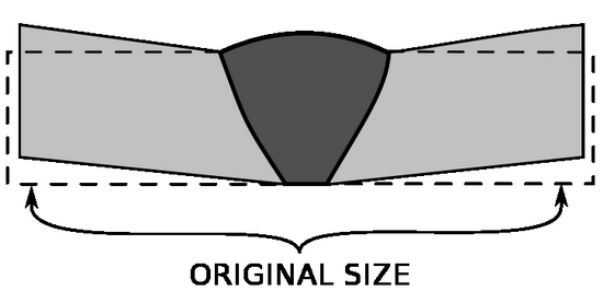
Complexity
Complexity or distortion is present to some extent in all types of welding, in many cases it is so small that it is hardly visible, but in some cases it is necessary to pay attention to the distortion that will subsequently occur before welding. The study and examination of distortion is very complex and what follows is summarized:
Factors for the occurrence of distortion:
1- Heating
2- Failure to use the necessary means to restrain the part.
3- Residual stresses in the part
4- Inappropriate properties of the workpiece
Causes of distortion When the metal under load strains or moves and deforms: Under light loading, metals remain elastic. (Return to their original shape or form after the load is removed) This is known as the elastic limit. Under very high loads, metals are stressed to the point where they can no longer return to their original shape or form, and this point is called the yield point (yield stress).
Metals expand when heated and contract when cooled. Metals are heated and cooled during welding, which causes sudden high stresses and distortion. If these high stresses exceed the elastic limit and also exceed the yield point, some permanent distortions are created in the metal. The metal’s stress is reduced at high temperatures. Distortion is an unwanted effect of the expansion and contraction of the heated metal.
Types of distortion
There are three main types of distortion:
1) Angular
2) Longitudinal
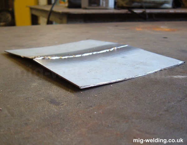
3) Transverse
Distortion control can be performed in three stages:
- Before welding
- During welding
- After welding
Distortion control before welding is performed by the following methods:
1) Spot welding
2) Clamping, fastening and holding
3) Complete and complete preheating
4) Proper initial assembly
Distortion control after welding:
1) Slow cooling
2) Flame straightening (reverse heating)
3) Annealing
4) Stress relief
5) Normalizing
6) Mechanical straightening
In metal building structures, methods 1 and 2 are usually applied more, and other methods are more commonly used in industrial work.
Annealing
A heat treatment process used to soften metals for cold working or machining. The workpiece or end product is usually heated in a furnace to a critical temperature (about 723-820°C for 0.52% carbon steel) and then slowly cooled.
Stress relieving
The uniform heating of welded parts to a temperature below the critical temperature, followed by slow cooling. This process lowers the yield point of the metal, thereby reducing residual stresses in the part.
Normalizing
A process for refining the grain structure of a metal, which improves its resistance to shock and fatigue. In normalizing, welded parts are heated above the critical temperature of 820°C for 0.25% carbon steel (approximately one hour for every 25 nm of thickness) and then cooled in air (direct working).
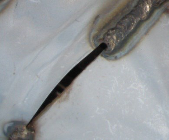
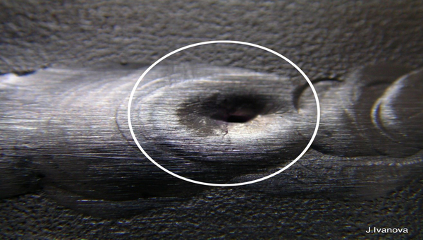
Black point – end-of-weld hole
There is a defect in welding that occurs at the end of the weld in the last pool and appears as a hole at the end of the weld. The reason for this defect is that when the welder raises the tongs at the end of welding, the electrons that move from the electrode towards the weld pool continue to move by the electrons when the electrode is raised to a certain distance and a hole is created when it hits the surface of the piece, but due to the high arc length, this part is not covered and as a result, this hole remains hollow.
How to prevent this defect
In order to prevent this defect from occurring in welding, the welder must step back a little when he reaches the end of welding and when he wants to remove the tongs from the weld pool, he must greatly reduce the angle of the tongs with the workpiece so that the movement of electrons from the electrode to the weld pool, which is vertical, is eliminated and as a result this defect does not occur.
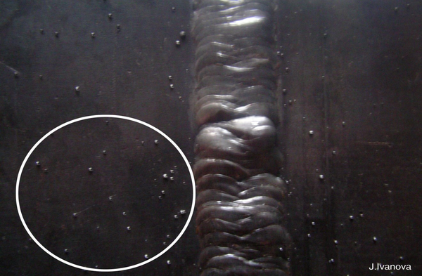
Spatter
The tiny droplets of metal that are thrown around from the welding area during fusion joints are called sparks or spatters. These droplets may come from the weld pool or more from the electrode and filler wire. When spherical and large grains of molten droplets are transferred from the electrode to the weld pool and create a bridge in the arc gap. A short circuit is created, the passage of current through which causes the bridge to melt extremely, which explodes and produces a shower of molten sparks around.
Sparking is increased by a number of reactions in various processes. The amount of excess gas produced by rapid cooling of the molten metal, the reaction between certain elements in the molten metal, for example sulfur, and some atmospheric gases in the weld pool area are examples of such sparking reactions. Coarse sparks in the manual electrode welding process are caused by excessive arc length, and fine sparks are caused by excessive current intensity.
Sparks often oxidize during flight in the atmosphere and only leave spots on the surface. Sparks stuck to the surface at a distance are often easier to clean with a wire brush or similar device, but sparks stuck near the joint path are not easily cleaned and make the appearance of the weld unsightly. On the other hand, spots left on the surface can cause complications similar to arc spots. In addition to the above, sparking and spatter are one of the problems that often annoy and annoy welders by burning their skin or clothing, and should be avoided if possible. This problem can often be reduced by adjusting the welding parameters (amperage, polarity, and voltage) or replacing the electrode.
Factors causing spattering:
- Long arc length: When the distance between the electrode and the workpiece is large, the molten particles coming from the electrode towards the metal. Temperature is about (metal temperature is approximately 1500 degrees Celsius), they must withstand the arc temperature which is about 5000 degrees Celsius, when the arc length is large, the molten drop must withstand the arc temperature over a longer distance but cannot explode on the way and is sprayed onto the workpiece, which results in this defect.
- High current intensity: When the current intensity is large, the temperature of the arc length increases (about 5000 degrees Celsius) and as a result, the molten drops cannot withstand this temperature and explode and are sprayed onto the workpiece.
- Damaged coating: When the electrode coating is damaged, the electrode cannot completely cover the molten area, and therefore, in the same part where the electrode does not cover properly, the arc loses its balance and causes molten metal to splash to different parts of the piece.
- Arc deviation: When the arc deviates, the balance in welding is lost and the arc becomes unstable, which causes more molten metal to splash.
Arc stricks
Usually, careless welders first rub the electrode on the work surface in one or more points to start the arc with a hand electrode, so that temporary arcs are created and, as the electrode tip heats up, it is easier to ignite the arc at the starting point of the welding operation. The points of momentary contact of the electrode with the work surface are observed as spots, which are actually a thin layer of the work surface that has melted due to the creation of a temporary arc and then cooled quickly. The cross-section of these spots under the microscope shows a very brittle martensitic structure that often has fine cracks. In addition, because the temporary arc time is very short, there is no opportunity for the electrode coating to melt and create a protective layer of slag or gas. As a result, this thin melted layer on the work surface comes into contact with oxygen and nitrogen from the atmosphere, and the lack of entry of some alloying or oxygen-removing compounds from the electrode coating into the pore area and many oxide particles are formed in this layer. These factors cause that if the workpiece is stressed in such a way that the mentioned spots are located in sensitive positions, they can become stress concentration points even at distances far from the connection point and lead to cracking or rupture of the workpiece.
Therefore, the welder must pay attention to firstly making the momentary contacts necessary to start the initial arc in each electrode on a scrap piece placed adjacent to the joint. Secondly, if this action is done inadvertently on the work, clean it by grinding it or cover it with a complete and sound weld. Thirdly, he should try to create these arc spots in the path of the joint so that these traces disappear after the arc reaches it.
Concavity in the weld pool
Reasons for the occurrence of this defect
1) High speed: When the welding speed is high, a channel is created by the collision of electrons from the electrode to the workpiece, and on the other hand, the molten materials that are responsible for filling this channel cannot do their job completely because they want to do this faster, so the channel is not filled completely and sufficiently, and this defect occurs.
2) High current intensity: When the welding current intensity is high, the molten splash also increases, and the penetration in welding increases, so there are two principles when the current intensity increases: on the one hand, the channel dug by the electrons has a high depth, and on the other hand, the molten particles that are responsible for filling this channel decrease in quantity due to high splash, and when they deposit in this channel, they cannot completely fill this channel, and this defect occurs.
Convexity
The reasons for this defect are exactly the opposite of concavity in welding.
1) The welding speed is low
2) The welding current is low
Postheat and preheat
When welding high-carbon steels with alloys, there is always a risk that the weld deposit and the heat-affected zone will form a hard and brittle metal called martensite. In this case, the metal will lose its ductility and may crack when cooled. By using preheat and postheat, the amount of martensite in the weld can be kept to a minimum.
Preheat and postheat raise the temperature of the metal adjacent to the weld, and as a result, the temperature difference between the weld and the adjacent metal is kept as low as possible. Low-carbon steels rarely require preheating. Since the hardenability of the steel is directly proportional to the amount of carbon and alloying elements, preheating temperatures will vary. Preheating up to 0.45% carbon equivalent (%) is optional Preheating temperature 200-400°F Carbon equivalent (%) above 0.60% carbon equivalent (%) Preheating temperature 400-700°F.
Postheating: The purpose of postheating is similar to preheating. In fact, postheating is used in conjunction with preheating by heating the weldment once the weld is complete. The workpiece temperature can be held at a high temperature to allow the weld to cool slowly. Like preheating, any postheating operation keeps the weldment area softer. Postheating temperatures and durations depend on the type and thickness of the steel. Temperatures can vary from 600°F for 10xx steels to 1200°F for 43xx steels, while the time required for postheating can vary from 5 minutes to several hours.
Effect of Elements in Steel
Various elements commonly found in metals have a distinct effect on their weldability. Some of these important elements and their effects on steel welding are:
- Carbon: Since it determines the hardenability of steel, it is the most important element in steel. The higher the carbon content, the harder the steel becomes. If carbon steel (above 0.30%) is welded and suddenly cooled, a brittle area is created next to the weld. In addition, if excess carbon is obtained from the welding gas mixture, the weld formed becomes so hard that it cracks easily. In general, the best weld is created when the carbon content in the steel is as low as possible.
- Manganese: In steel, it increases hardenability and tensile strength. However, if the manganese content is above 0.60%, and especially if it is combined with a high degree of carbon, weldability will definitely decrease. In this condition, additional cracking will usually occur. If the manganese content is too low, internal porosity and cracking may develop. The best welding results are obtained when the steel contains 0.40 to 0.60 percent manganese.
- Silicon: Used to improve the quality and tensile strength of steel. High levels of silicon, especially in combination with high carbon, result in cracking.
- Sulfur: Often added to improve the machining properties of steel. However, its amount is kept low in other types of steel (0.035 percent and maximum 0.05 percent) because high sulfur content increases the likelihood of cracking. High sulfur machining steels are usually welded with low hydrogen electrodes without any difficulty.
- Phosphorus: It is considered an impurity in steel and therefore its amount should be kept as low as possible. Phosphorus levels above 0.04% cause the weld to become brittle.
- Other elements (nickel, chromium, vanadium, etc.) have various effects on the weldability of metals. Welding of these alloys must be done with special care and preheat and postheat are usually required to prevent the formation of hard and brittle areas in the weld.